1. Try to avoid ferromagnetic objects and equipment with strong electromagnetic fields (large motors, large transformers, etc.), so as not to affect the magnetic field and flow signal of the sensor.
2. Should be installed in a dry and ventilated place as far as possible, avoid the sun and rain, the ambient temperature should be -20 ~ +60℃, and the relative humidity is less than 85%.
3. There should be plenty of space around the flowmeter for easy installation and maintenance.
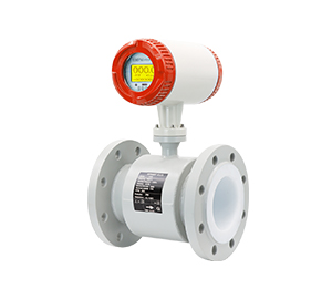
Electromagnetic flowmeter installation recommendations:
01 Ensure that a full pipe is installed
The measuring tube of the electromagnetic flowmeter must be in full tube state, and non-full tube state cannot occur. If the pipe is not full or the outlet is empty, the sensor should be mounted on a siphon.

Avoid installation upstream of downward pipes

Avoid at the highest point of the pipeline, easy to gather bubbles
02 Horizontal and vertical installation
The sensor can be installed horizontally and vertically, but it should be ensured that the influence of deposits and bubbles on the measuring electrode is avoided, and the axial direction of the electrode is kept horizontal. When installing on a horizontal pipe, the two measuring electrodes should not be directly above and below the pipe. When installed vertically, the fluid should flow from bottom to bottom.
The inlet straight pipe section should be larger than 5D, and the outlet straight pipe section should be larger than 2D. Specific installation requirements should be installed according to the electromagnetic flowmeter instructions. The insert type straight pipe section should be ≥ 20 D, and the outlet straight pipe section ≥7D(D is the nominal caliber of the sensor).

Horizontal piping installation

Vertical piping installation
03 Exit is installed when the air is empty
When the outlet is empty, the sensor should not be installed in the pipe empty, should be installed at a lower place. When the sensor is installed under the pipeline, ensure that the sensor is filled with liquid and does not appear empty pipe.

The outlet of the pipeline is installed at the time of emptying
04 Serial and parallel installation
If several sensors need to be sequentially connected in series on the same pipe, the distance between each sensor should be at least 2 sensor lengths. If more than two sensors are installed in parallel with each other, the sensor distance must be greater than 1m.
05 Installation between bends, valves and pumps
In order to ensure the stability of the measurement, a straight pipe section should be installed at the front and back of the sensor, the length of which is given in the figure below. If this is not possible, the current stabilizer should be used or the cross-sectional area of the measuring point should be reduced.

Installation between bends, valves and pumps
In order to avoid negative pressure, the sensor can not be installed in the pump inlet, but should be installed in the pump outlet.

Grounding diagram of a sensor installed on a metal pipe
06 Install bypass pipes
In the installation of the flow meter pipe should have a valve that can cut off the medium in the pipe to facilitate daily maintenance and maintenance. When the process does not allow flow interruption. A bypass pipe can be added to the pipe where the flow meter is installed.
07 Install in the specified direction
When the flow meter sensor has a clear flow mark, it should be installed in the calibration direction.
08 Cable inlet, cable and conduit
Flow meter inlet, cable and threading pipe should be bent downward, and open at the lowest place to avoid water, resulting in short circuit.
09 Welding Flange
When the flow meter is installed, the flange should be welded first, and then the flow meter is installed. The flange can not be directly welded with the flow meter sensor, so as not to burn the lining with welding slag.
10 Distance between transducer and sensor
The signal cable between the transducer and the sensor cannot be larger than 50m, and the signal cable must be threaded with galvanized pipes.
11 Grounding measures for the sensor
The flow signal generated by the sensor is very small, and only a few millivolts at full scale, so the sensor should be well grounded. The grounding requirements of the electromagnetic flowmeter have two aspects: from the working principle of the electromagnetic flowmeter and the flow induction signal current loop to analyze, the grounding terminal of the sensor and the converter must be the same potential as the measured medium.
Ground, zero potential to the earth, reduce external interference.
Under normal circumstances, the process pipe is a metal pipe, itself is grounded, this requirement is easy to meet. However, in the case of large interference from the external electromagnetic field, the electromagnetic flowmeter should be equipped with a ground device. The ground wire is multi-strand copper wire with a cross-section greater than 5mm2. The ground wire of the sensor must not be connected to the public ground wire of the motor or other equipment to avoid the influence of leakage current. The ground resistance must be less than 10 ohms.
The sensor is installed on a plastic pipe or a pipe with an insulating lining. A ground ring, a ground flange, or a short tube with a ground electrode should be installed at both ends of the sensor. Ground the sensor according to the following figure.

Grounding diagram of a sensor installed on a metal pipe
Make the measured medium flowing in the tube and the ground short circuit, with zero potential, otherwise, the electromagnetic flowmeter can not work normally.

Install grounding diagrams on plastic pipes or pipes with an insulating lining
Electromagnetic flowmeter fault and troubleshooting methods
01 Acceptance of electromagnetic flowmeter
The acceptance phase is generally the inspection of sensors, converters and connecting cables. The sensor can be measured according to the air traffic control condition:
① electrode insulation performance;
② excitation coil resistance and insulation performance;
③ Check the good lining material;
For converter detection, analog signal generator should be used, do not check the converter output after connecting the converter with the sensor, because this is an empty pipe, and the output information and display information are random. For connecting cables, check whether the cable type and length meet requirements.
02 Initial assembly and debugging of electromagnetic flowmeter
The following analyses and checks should be focused:
① Whether the working conditions of the instrument meet the requirements (humidity, pressure, flow rate, protection level);
② Whether the instrument selection is correct;
③ Whether the instrument installation is reasonable (grounding, front and rear straight pipe section, wiring) taboo five installation methods;
Gas gathering point – the accumulation of bubbles should be avoided
Non-full tube – Ensure full tube condition at the time of measurement
Siphon mouth – cannot produce siphon
Front valve – The regulator should be installed downstream of the flow meter
After pumping – upstream pump to remove negative pressure
External interference introduced by the connecting cable should also be considered, and the failure of the instrument itself should not be excluded;
After power-on, the zero point must be adjusted in the static state of the electromagnetic flow sensor full of liquid.
Inspection of electromagnetic flowmeter after operation
Zero check for regular stop flow under conditions of use:
① Sensor electrode wear, corrosion, leakage, scaling. Especially for precipitated, easily contaminated electrodes, containing solid phase of the non-clean liquid;
② Excitation coil insulation decline;
③ The insulation of the converter decreases;
④ converter circuit fault;
⑤ Connection cable damaged, short circuit, damp;
⑥ Do not rule out new changes in instrument operating conditions.
Common faults and troubleshooting methods in electromagnetic flowmeter operation:
1. Instrument flow no signal output?
Reason analysis:
① The instrument power supply is not normal;
② The cable connection is abnormal;
③ The liquid flow condition does not meet the installation requirements;
④ The sensor parts are damaged or the measurement wall has an adhesive layer;
⑤ The converter component is damaged.
Solution:
① Confirm that the power supply has been connected, check whether the output voltage of the power circuit board is normal, or try to replace the entire power circuit board to determine whether it is good or bad.
② Check whether the cable is in good condition and whether the connection is correct.
③ Check the liquid flow direction and whether the liquid in the tube is full. For the electromagnetic flowmeter that can be measured in positive and negative directions, although it can be measured if the direction is inconsistent, the set display flow is inconsistent in positive and negative directions, which must be corrected. If the sensor is removed, the arrow direction on the sensor can also be changed and the display instrument symbol can be reset. The pipeline is not full of liquid is also caused by the sensor installation location, and measures should be taken during installation to avoid causing the liquid in the pipeline to be dissatisfied with the pipe.
④ Check whether the inner wall electrode of the variable speed feeder is covered with a liquid scarring layer. For the measurement liquid that is prone to scarring, it should be cleaned regularly.
If it is judged that the fault is caused by the damage of the converter component, the damaged component can be replaced.
2. Output value fluctuates
Reason analysis:
Most of these faults are caused by the influence of the measuring medium or the external environment, and the faults can be eliminated by themselves after the external interference is removed. In order to ensure the accuracy of measurement, such failures can not be ignored. In some environments, due to the vibration of the measuring pipe or liquid, it will cause the circuit board of the measuring meter to loosen, and it can also cause fluctuations in the output value.
Solution:
① Confirm whether it is the reason for the process operation, the fluid does pulsate, at this time the flow meter only truthfully reflects the flow condition, and the fault can be eliminated by itself after the pulsation is over.
② Electromagnetic interference caused by external stray current. Check the operating environment of the instrument whether there are large electrical appliances or welding machines in operation, to ensure that the instrument is grounded and the operating environment is good.
③ When the pipeline is not filled with liquid or the liquid contains bubbles, both are caused by process reasons. At this time, the technician can be asked to confirm that the output value can return to normal after the liquid filling tube or the bubble is flattened.
④ The transmitter circuit board is a plug-in structure, because the field measurement pipeline or liquid vibration is large, often cause the flow meter power board loose. If it is loose, the flow meter can be disassembled and the circuit board can be fixed again.
3. Signal output when there is no flow after power-on?
Reason analysis:
① Input shielding or grounding is poor, electromagnetic interference is introduced;
② The instrument is close to the strong electric equipment or high frequency pulse interference source;
③ The pipeline has strong vibration;
④ the converter agility is too high;
Treatment method:
① Improve shielding and grounding, eliminate electromagnetic interference;
② Separate the installation of interference sources and take isolation measures to strengthen the power filter;
③ Take shock absorption measures, strengthen signal filtering to reduce the agility of the amplifier;
④ Reduce agility and improve trigger level.
4. Large measurement error
Reason analysis:
① The pressure in the tube is too high;
② Engineering pressure selection divergence error;
③ Seal damage;
④ The sensor is eroded;
Treatment method:
① Adjust the high pressure and change the installation position;
② Choose a high grade engineering pressure sensor;
③ Replace the seals;
④ Adopt anti-corrosion and protection measures.