Principle, selection and installation of electromagnetic flowmeter
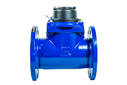
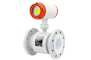
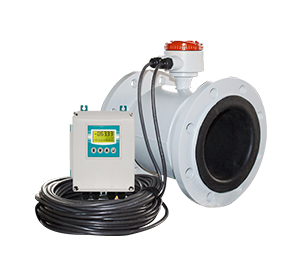
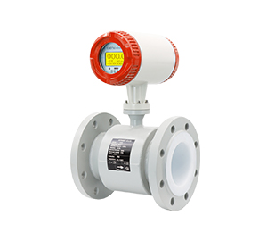
Electromagnetic flowmeter is based on Faraday’s law of electromagnetic induction made of a measurement of conductive liquid instrument. The electromagnetic flowmeter is composed of three parts: sensor, converter and cable connection line. If the cable connection is short, install it in the flow meter housing.
The working principle of electromagnetic flowmeter:
Electromagnetic induction law:
The working principle of the electromagnetic flowmeter is based on Faraday’s law of electromagnetic induction: when the conductor (liquid) passes through the magnetic field, an electromotive force will be induced in the conductor, and the size of the electromotive force is proportional to the flow rate of the liquid.
Electromagnetic coil:
Electromagnetic flowmeters include a pipe through which liquid flows. Excitation coil and detection coil around the pipe.
Electromotive force measurement:
Electrically charged particles (usually ions) present in a liquid create an electromotive force when they move in a magnetic field. The detection coil measures the magnitude of this electromotive force and converts it into information about the flow rate of the liquid.
Calculate velocity and flow:
By measuring the size of the electromotive force, the electromagnetic flowmeter can calculate the flow rate of the liquid. Combined with the cross-sectional area of the pipe, a value for the flow rate (the volume of fluid passing through the pipe per unit time) can be obtained.
Induced electromotive force is generated between the two electrodes:
e=KBDv
It can be obtained that the volume flow rate of the pipeline is:
qv= πeD/4KB
As can be seen from the above formula, the volume flow qv is linearly related to the induced electromotive force e and the inner diameter of the measuring tube D, and inversely proportional to the magnetic induction intensity B of the magnetic field, independent of other physical parameters. This is the measurement principle of the electromagnetic flowmeter.
The electromagnetic flowmeter has a series of excellent characteristics, which can solve the problems that other flowmeters are not easy to apply, such as the measurement of dirty flow and corrosion flow.
Advantages of electromagnetic flowmeter:
① The measurement channel is a smooth straight pipe, which is not blocked, and is suitable for measuring liquid-solid two-phase fluids containing solid particles, such as pulp, mud, sewage, etc.;
② No pressure loss caused by flow detection, good energy saving effect;
The measured volume flow rate is not significantly affected by changes in fluid density, viscosity, temperature, pressure and conductivity.
④ Large flow range, wide caliber range;
⑤ Corrosive fluids can be applied.
Disadvantages of electromagnetic flowmeter:
① Can not measure the conductivity of very low liquids, such as petroleum products;
② Can not measure gas, steam and liquids containing large bubbles;
③ Can not be used for higher temperatures.
Electromagnetic flowmeter selection:
The following are the selection steps of electromagnetic flowmeters:
Step 1: Collect data.
① the name of the measured flow body;
② Maximum flow rate and minimum flow rate;
③ Maximum working pressure;
④ Maximum temperature and minimum temperature.
Where the maximum flow and minimum flow must conform to the table below:
The flow calculation formula is as follows:
Q = Vπ(D/2)²
Analyzing the above formula,
Q is the liquid flow rate (m³/h);
V is the liquid flow rate (m/s) (the range is generally 0.1~15 m/s);
D is the inner diameter of the pipe (mm).
The following points must be noted in the collection of data:
① The actual maximum working pressure must be less than the rated working pressure of the flowmeter.
② The maximum and minimum working temperature must meet the temperature requirements specified by the flow meter.
③ Determine whether there is negative pressure.
④ The user can choose the corresponding electromagnetic flowmeter according to the flow range table, if the internal diameter of the selected electromagnetic flowmeter is not consistent with the internal diameter of the current process pipe, the pipe should be shrunk or expanded. In the case of pipe shrinkage, consideration should be given to whether the pressure loss due to pipe shrinkage will affect the process flow.
⑤ From the product price consideration, you can choose a smaller caliber electromagnetic flowmeter, relatively reduce investment.
⑥ When measuring clean water, the economic flow rate is 1.5~3m/s; When measuring the solution that is easy to crystallize, the flow rate should be appropriately increased, and it is appropriate to 3~4m/s to play the role of self-cleaning and prevent adhesion deposition. When measuring abrasive fluids such as pulp, the flow rate should be appropriately reduced, 1.0~2m/s is appropriate to reduce the wear of the lining and electrode.
Step 2: Electrode material selection.
The material of the electrode should be selected according to the corrosiveness of the flow being measured, and the corrosion manual can also be consulted, and the experiment should be done for special fluids.
Electrode material and its corrosion resistance:
| Materials | Corrosion resistance: |
| Molybdenum stainless steel | Nitric acid, greenhouse < 5% sulfuric acid, boiling phosphoric acid, formic acid, alkali solution, sulfite under certain pressure, sea water, acetic acid |
| Hastelloy C(HC) Hastelloy B(HB) | Resistance to oxidizing acid, oxidizing salt, seawater, non-oxidizing acid, non-oxidizing salt, alkali, normal temperature sulfuric acid |
| Titanium (Ti) | Seawater, various chlorides and hypochlorites, chlorinated acids (including fuming nitric acid), organic acids, bases |
| Tantalum (Ta) | Other chemical media other than hydrofluoric acid, fuming sulfuric acid and alkali, including hydrochloric acid, nitric acid and lt at boiling point; 175℃ sulfuric acid |
| Platinum (Pt) | All kinds of acids, bases, salts, not including aqua regia |
Step 3: Lining material selection.
Lining materials should be selected according to the corrosion, wear and temperature of the measured medium
Lining material selection
| Lining material | Name | Symbol | Property | Maximum operating temperature /℃ | Applicable liquid | Applicable diameter (mm) |
| Rubber | Neoprene rubber | CR | Medium wear resistance, corrosion resistance to low concentration of acid, alkali and salt | <80 | Tap water, industrial water, sea water | DN50 ~2200 |
| Polyurethane rubber | PU | Excellent wear resistance, poor acid and alkali resistance | <80 | Pulp, mineral pulp and other slurry | DN25 ~500 | |
| Fluoroplastics | Polytetrafluoroethylene | F4 or PTFE | Chemical properties are very stable, resistant to boiling hydrochloric acid, sulfuric acid, aqua regia, concentrated alkali corrosion | <180 | Highly corrosive acid, alkali and salt liquids | DN25 ~1200 |
| Polyperfluorinated ethylene propylene translation: Teflon FEP | F46 or FEP | The chemical properties were slightly inferior to F4 | <120 | Corrosive acid, alkali and salt liquids | DN15 ~200 | |
| Ethylene tetrafluoroethylene copolymer | Fao or ETFE | The chemical properties were slightly inferior to F4 | < 120 | Corrosive acid, alkali and salt liquids | DN250 ~2200 | |
| Plastic | Polythene | PO | Chemically stable | <60 | Sewage | DN50 ~2200 |
| Polyphenylene sulfide | PPS | <110 | Hot water | DN50 ~2200 |
Step 4: The choice of protection level.
The protection level of electromagnetic flowmeter generally has the following three kinds:
IP65: Anti-spray type, allowing the faucet to spray water to the sensor from any direction, the spray pressure is 30kPa, the water output is 12.5L/s, the distance is 3m, the water intake of the shell will not reach harmful degree, the instrument is not affected.
IP67: Waterproof type for a short time, the sensor is immersed in water, the amount of water into the housing will not reach harmful levels in a short time, and the instrument is not affected.
IP68: Submersible type, the sensor is immersed in water 1m, after continuous diving, the amount of water into the shell will not reach harmful levels, and the instrument is not affected.
Installation of electromagnetic flowmeter:
The correct selection of the installation point and the correct installation of the electromagnetic flowmeter are very important links, if the error in the installation link, the light will affect the measurement accuracy, the heavy will affect the service life of the electromagnetic flowmeter, and even damage the electromagnetic flowmeter.
1) Special attention should be paid to mechanical installation when selecting the installation position:
① The axis of the measuring electrode must be approximately in the horizontal direction, the measuring pipe must be completely filled with liquid, the meter must have at least 5D (D is the inner diameter of the meter) length of the straight pipe section, and the rear must have at least 3D (D is the inner diameter of the meter) length of the straight pipe section. (Figure 2-11)

Figure 2-11 Mechanical installation of the electromagnetic flowmeter
② The flow direction of the fluid is consistent with the arrow direction of the flowmeter; If there is a vacuum in the pipeline, it will damage the lining of the flow meter, and special attention should be paid to it. There should be no strong electromagnetic field near the flowmeter; There should be ample space near the flow meter for installation and maintenance; Install the flow timing of the polytetrafluoroethylene lining, the bolts connecting the two flanges should be evenly tightened, otherwise it is easy to crush the polytetrafluoroethylene lining, it is best to use a torque wrench.
③ It should be installed at the lower part of the horizontal pipeline and the vertical upward part (see Figure 2-12), and avoid installation at the highest point of the pipeline and the vertical downward part (see Figure 2-13); It should be installed at the elevation of the pipeline (see Figure 2-14).

Figure 2-12 Installing the cable at the lower part of the horizontal pipe

Figure 2-13 Avoid installing the pipe at the highest point and vertically down the pipe

Figure 2-14 Installing the cable at the rise of the pipe
When the open discharge pipe is installed, it should be installed at the lower part of the pipe.
④ If the pipe drop exceeds 5m, install an exhaust valve downstream of the sensor (see Figure 2-15); The control and cut-off valves should be installed downstream of the sensor, not upstream of the sensor (see Figure 2-16). The sensor must not be installed at the inlet of the pump, but should be installed at the outlet of the pump (see Figure 2-17).

Figure 2-15 Installing an exhaust valve downstream of the sensor

Figure 2-16 Installing the control valve and cut-off valve downstream of the sensor

Figure 2-17 Installation positions of the sensor and pump
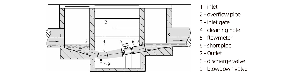
Figure 2-18 shows how to install a flowmeter in a measuring well.
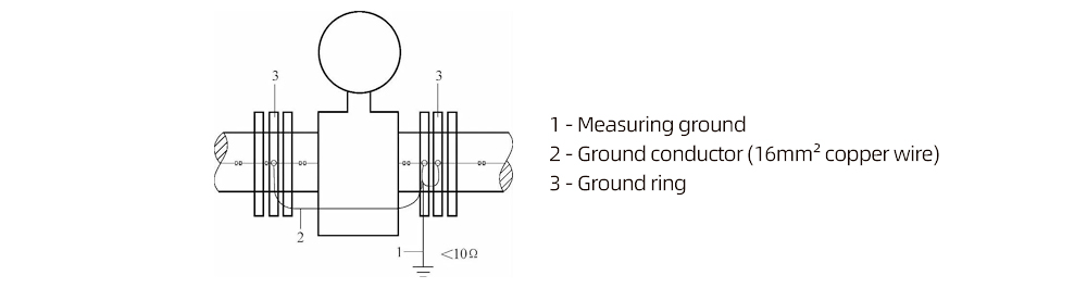
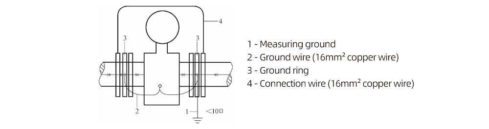
2) Electrical grounding Figure 2-19 shows:
In order to prevent external interference, the electromagnetic flowmeter requires that the measured medium, the user pipeline and the instrument housing must be in a potential that is connected to the “ground”, the instrument must be connected to an independent ground point, other electrical equipment is not allowed to connect to the same ground line, the ground resistance should be less than 10Ω. There are two kinds of grounding methods: external grounding and internal grounding. The so-called external grounding is the grounding ring, and the so-called internal grounding is the grounding electrode in the multi-electrode.
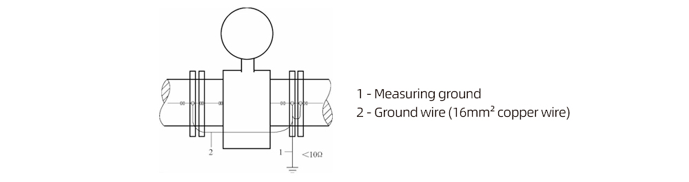
Figure 2-19 Grounding of the flowmeter
① When the instrument is installed on an internal unpainted or unlined metal pipe, the ground wire can be connected to the two pipe flanges, thus forming a reliable contact between the pipe and the liquid.
② When the instrument is installed on a plastic pipe or a pipe with inner wall insulation, a ground ring should be installed at the outlet and entrance of the sensor, or an internal ground electrode should be used to connect the measurement ground with the liquid.
③ The instrument is installed on the cathodic protection pipeline, and the pipeline with electrical corrosion protection is usually insulated inside and outside to make the liquid non-conductive ground to the ground.
The following points must be paid attention to when installing:
(1) The two ends of the sensor should be equipped with a suitable ground ring, which relies on the insulation of the seal and the sensor flange of the pipe flange;
(2) The ground ring must be connected to the sensor and measuring ground cable using a copper wire with a cross-sectional area of 16mm² (see Figure 2-20).
(3) The two pipe flanges connected to the instrument must be connected with a copper wire with a cross-sectional area of 16mm² (see Figure 2-21).
(4) The shaft sleeve and washer of insulating material are used to insulate the flange connecting bolt from the flange.
3) Electrical wiring
If the split-type installation is used, the connected signal cable is customized special cable, the shorter the cable, the better;
Excitation cable can choose YZ medium rubber sleeve cable, its length is the same as the signal cable;
Signal cables and power cables must be strictly separated, can not be laid in the same pipe, can not be laid in parallel, can not be twisted together, should be worn separately in the steel pipe;
The signal cable and the excitation cable should be as short as possible. Do not roll the redundant cables together. Cut off the redundant cables and weld the connectors again.