Static Balancing Valve VS Dynamic Differential Pressure Balancing Valve
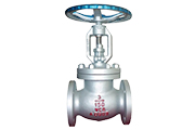
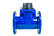
What is Static Balancing Valve?
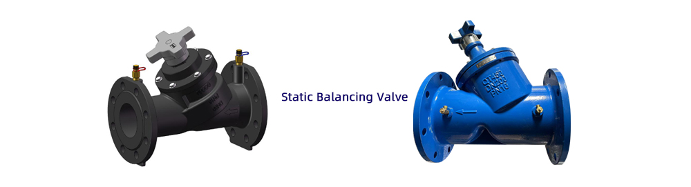
System Application of Static Balancing Valve:
CM series balancing valves can be widely used in heating and cooling systems, domestic water systems, cold tower circulation systems, dehumidification and other hydraulic circulation systems. It calculates the resistance of the primary main pipeline and each graded pipeline, and then uses a differential pressure gauge to measure and adjust the Kvs value to balance the resistance and distribute the flow.
It is used in conjunction with a differential pressure control valve to stabilize the pressure difference between the supply water and the return water, automatically eliminate the interference of system pressure changes, and keep the pressure difference between the static balancing valve and the differential pressure control valve within a stable value. This ensures that the valve downstream of the return water will not produce overflow or water shortage to achieve the best working state.
Technical Parameters of Static Balancing Valve:
Design standard: GB/T 28636-2012, BS7350;
Structural length: GB/T12221 Series 1, EN558-1 Series 1;
Connection flange: GB/T17241.6, ISO7005;
Threaded connection standard complies with EN10226;
Pressure rating: PN10/PN16
Working temperature: -10~120℃;
Comply with PED and valve special equipment manufacturing license
Perform relevant tests in accordance with the requirements of the “Static Balancing Valve Pressure Test Specification”
Installation Instructions and Precautions of Static Balancing Valve:
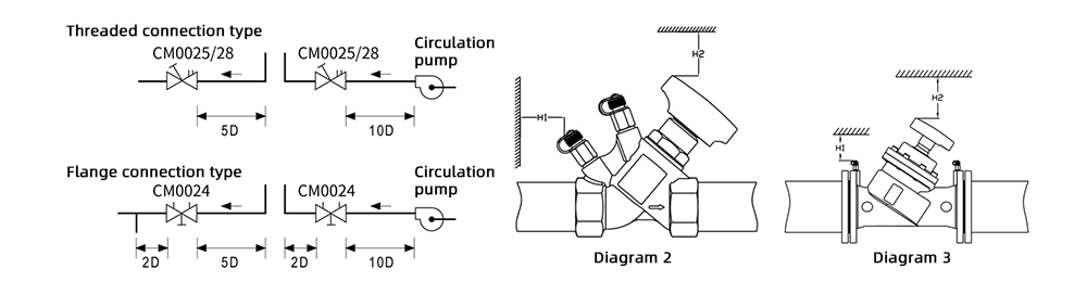
① The balancing valve should be installed in a location where manual adjustment, pressure difference/flow measurement, and draining are convenient. It can be installed either horizontally or vertically. To ensure more accurate balancing flow, a straight pipe section must be installed at both the upstream and downstream ends of the valve. The required length of the straight pipe is shown in the diagram. The valve must be installed following the flow direction indicated by the arrow on the valve body.
② Before installation, remove the flange sealing cover and ensure there are no debris in the system.
③ Ensure that the flow direction of the medium aligns with the direction marked on the valve body.
④ The valve body installation direction is flexible, and the balancing valve can be installed either on the supply or return pipeline. Only one valve needs to be installed per loop. It is recommended to install the balancing valve on the return pipeline with lower water temperature.
⑤ The balancing valve on the main pipeline should be installed in the direction of the pump outlet. The degree indicator on the handle should face the direction visible to the commissioning personnel for easier adjustment. Ensure that no obstacles are in front of the measurement port on the valve body to avoid obstructing the connection of testing instruments during commissioning.
⑥ Ensure sealing between flanges. The measuring port should be installed before the valve is filled with water.
⑦ Once the valve opening degree is set, do not alter it at will. The balancing valve has a shut-off function, eliminating the need for additional shut-off valves.
⑧ To prevent damage to the pressure test port, it should only be installed after the valve is fully mounted. During installation, follow the principle that the red end is for the supply side, and the blue end is for the return side.
⑨ To ensure proper operation, when CM0024/25/28 valves are connected to elbows or pumps, a certain length of straight pipe must be kept. When connected to an elbow, follow the 5D rule before the valve and 2D rule after the valve. When connected to a pump, follow the 10D rule. See Diagram 1.
When installing the valve, leave sufficient space for adjustments as shown in Diagram 2 and Diagram 3:
DN15-DN50: H1 > 200mm, H2 > 170mm
DN50-DN150: H1 > 200mm, H2 > 230mm
DN50-DN150: H1 > 200mm, H2 > 400mm
Product Applications of Static Balancing Valve:
Building HVAC or Heating Networks
In building HVAC and heating systems, in order to meet energy-saving requirements, it is necessary to ensure that all main and branch pipelines meet the designed flow rates. Therefore, balancing valves should be installed on the main, dry, vertical, and branch pipes.
District Heating Networks
District heating networks, typically from a boiler room or heat station supplying heat to multiple buildings, may face uneven flow distribution due to differing distances from the heat source. Without effective equipment to eliminate excess pressure in the shorter loops, the flow distribution will not meet design specifications, causing overheating at the near side and underheating at the far side. Balancing valves should be installed on each dry pipe and branch pipe to ensure balanced flow between each main pipe and building.
Heat Exchange Units or Chillers
When heat exchange units or chillers are installed in parallel, if the flow rates of the units do not match their rated flow, the units cannot operate efficiently. In such cases, balancing valves should be installed on each heat exchange or chiller unit to ensure that each unit operates at the designed flow rate, ensuring safe and normal operation.
Thermal Stations
In systems where thermal power stations or boiler rooms supply hot water or steam to multiple heating stations, balancing valves should be installed on the primary loop side of each heating station to ensure the required flow. Additionally, to guarantee the flow in each secondary loop is maintained at the designed value, balancing valves should also be installed on each secondary loop of the thermal station.
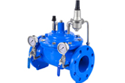
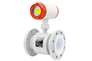
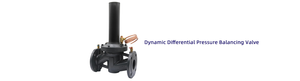
Product Description of Dynamic Differential Pressure Balancing Valve:
The DPCV series dynamic differential pressure balancing valve contains a balancing valve core, high-performance diaphragm, and spring composed of adynamic differential pressure balancing valve component. It is a dynamic differential pressure control valve that ensures constant differential pressure on the load or circuit, helping to provide stable conditions for heating and cooling systems, thereby improving the stability and accuracy of the control valve, extending its service life, reducing noise, and facilitating balance regulation.
Characteristics of Dynamic Differential Pressure Balancing Valve:
Easy to Operate
Set the target differential pressure value through the scale, with simple and intuitive operation.
Stable Accessories
High-performance springs and diaphragms.
Beautiful and Reliable Design
Compact design, easy to install exhaust hole design allows for easy removal of internal air.
Differential Pressure Range Can Be Set
Segmented design of differential pressure control range (high/low-pressure difference models), with higher precision in pressure difference control.
Technical Specifications of Dynamic Differential Pressure Balancing Valve:
Size: DN65-DN250
Pressure rating: PN10/PN16/PN25
Maximum differential pressure: ≤400KPa
Setting control range: 20*-80kPa or 40*-160kPa(*initial setting)
Working Temperature: -10℃ to 120℃
Working medium: Water or neutral liquid, ethylene glycol solution (0-50%)
Surface treatment: Body with epoxy resin coating/spray paint
Length: According to ISO5752 Series 1, BS 2080,EN558-1
Flange: ISO 7005-2/EN 1092-2
Material:
①Body:Ductile iron EN-GJS-450
②Disc:SS304
③Stem:SS304
④Spring:SS304
⑤O-ring:EPDM
⑥Diaphragm:EPDM+reinforced fiber
Design of Dynamic Differential Pressure Balancing Valve:
The dynamic differential pressure control valve can be used alone or in combination with the static balancing valve. The water few direction must be consistent with the arrow direction of the valve body. The line should be flushed prior to installation and it is recommended to install a filter at the front end. The capillary tube should be connected in the horizontal position of the water supply line, but not under the pipe, to prevent the dust particles blocked, the capillary signal tube must be installed and connected before the water system pressure test, and the blocking valve must be rotated. Otherwise, too much pressure will cause damage to the differential pressure regulator.
The dynamic differential pressure control valve installed valve is installed on the return water pipe, and used with the static balance valve, the static balance valve is installed with the water supply pipe as shown in the following figure.
①inlet pipe
②return pipe